HVAC cheat sheet: refrigerant PT chart, superheat and subcooling targets, and AC and heat pump troubleshooting charts (free PDF, Word and Google Docs)
- Free. No signup and no email asked; the links below go straight to the file.
- Deepsel is our product. It tracks HVAC maintenance agreements, and the last section says so.
- The pressures come from the refrigerant makers' published tables and the targets from the equipment makers' installation instructions. The rating plate, the charging chart and the instructions for the unit in front of you override every number on this page.
- Written for technicians. If you own the system, what to ask your HVAC technician lists the readings to ask for on the invoice.
An HVAC cheat sheet is a short reference a technician keeps in the truck for the numbers a service call depends on. This one has a refrigerant pressure-temperature (PT) chart for R-22, R-410A, R-32 and R-454B, target superheat and subcooling from current manufacturer instructions, and HVAC troubleshooting charts for air conditioners and heat pumps. R-454B has two saturation pressures at each temperature, bubble and dew, and the chart prints both. Systems with a fixed orifice (piston) and systems with a thermostatic expansion valve (TXV) have separate charts. Each number is cited to the published table, manual or standard it comes from.
Get it three ways: make your own copy in Google Docs (one click, lands in your Drive), download the Word version (.docx), or download the PDF. You can also read it in Google Docs first without copying anything. The PDF is seven pages on US Letter with one section on each page, so you can print only the pages you need. The pages are listed below. The checklists that put these numbers to work on a maintenance visit are on the free HVAC checklists page.
The pages that rank for these searches are of two kinds. The contractor pages from Green Leaf Air, A.J. Perri and Arthur Heating & Air are written for homeowners: check the thermostat, the breaker and the filter, clear the outdoor unit, then call a professional.1, 2, 3 Green Leaf's adds a six-row table of arrows for pressures, superheat, subcooling and amps. The table has no numbers in it, and its liquid-line restriction row matches its undercharge row arrow for arrow, so it cannot separate the two faults that a subcooling reading separates.1 The technician references are images and PDFs: HVAC School's one-page diagnostic quick sheet, the refrigerant makers' PT charts, and charts photographed and passed around r/HVAC. "Been in 15 years. I've got one in my truck and still peek at it," one technician wrote under a posted chart.4 Another wrote of his heat pump sheet: "It's a photocopy of a crumpled piece of paper and hard to read, but still very useful."5 The complaint in the same threads is specific. "TXV or fixed is a big issue," a reply said of a chart that combined the two.5 This sheet keeps fixed-orifice and TXV systems apart, prints its numbers as text tables that copy and print cleanly, and names the source of each one.
What is on the HVAC troubleshooting cheat sheet PDF, page by page
The printable file is a seven-page HVAC troubleshooting guide in PDF, Word and Google Docs. All three formats come from the same Google Doc and carry the same text. The file is a condensed version of this page: it prints the PT chart in full, shortens the other tables and notes, and leaves the source list here. Each link below goes to the matching section of this page.
- Refrigerant PT chart: saturation pressures for R-22, R-410A, R-32 and R-454B from -40 to 150°F, with R-454B's bubble and dew columns.
- Superheat and subcooling: the two formulas, where to take each reading, subcooling targets from current manufacturer manuals and a target superheat table for fixed-orifice systems.
- HVAC troubleshooting chart, refrigerant side: how the pressures, superheat, subcooling and amps read on each fault, on one chart for fixed-orifice systems and one for expansion-valve systems.
- AC troubleshooting chart by symptom: 15 symptoms, each with its likely causes and what to check first.
- Heat pump troubleshooting chart: heating-mode readings by fault, and six heat pump symptoms with causes and first checks.
- Heat pump defrost: what starts and ends defrost on five manufacturers' controls, how to force a test defrost, and what is normal in heating mode.
- Rules of thumb and formulas: expected saturation temperatures, subcooling, temperature split, airflow and static pressure, and the formulas for capacity, airflow, gas input and capacitor checks.
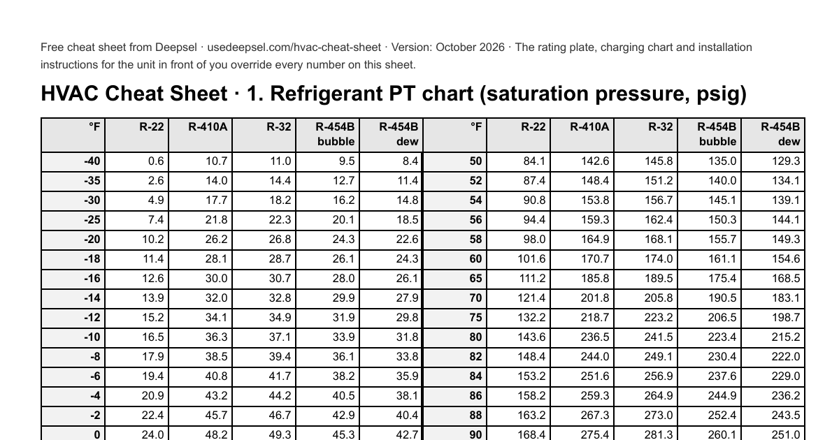
Refrigerant PT chart for R-22, R-410A, R-32 and R-454B
A refrigerant PT chart (pressure-temperature chart) lists the saturation pressure of a refrigerant at each temperature. Saturation is the state in which liquid and vapor exist together, as the refrigerant boils in the evaporator or condenses in the condenser. To use the chart, read the pressure on the gauge, find it in the column for the refrigerant, and take the temperature in that row as the saturation temperature. Superheat and subcooling are both measured from that temperature. The pressures below are gauge pressures in psig from Chemours' Pressure-Temperature Guide for A/C. R-454B's two columns are from Chemours' Opteon XL41 table, which gives the saturated liquid and saturated vapor pressure at every degree.6, 7 We checked every row against Arkema's Forane chart: R-454B matches to the tenth, and R-22, R-32 and R-410A agree within 0.1 psi except where the two makers print different columns for R-410A, which the notes under the tables explain.8
Low-side PT chart: -40 to 60°F (suction line and heat pump outdoor coil)
| °F | R-22 (psig) | R-410A (psig) | R-32 (psig) | R-454B bubble, liquid (psig) | R-454B dew, vapor (psig) |
|---|---|---|---|---|---|
| -40 | 0.6 | 10.7 | 11.0 | 9.5 | 8.4 |
| -35 | 2.6 | 14.0 | 14.4 | 12.7 | 11.4 |
| -30 | 4.9 | 17.7 | 18.2 | 16.2 | 14.8 |
| -25 | 7.4 | 21.8 | 22.3 | 20.1 | 18.5 |
| -20 | 10.2 | 26.2 | 26.8 | 24.3 | 22.6 |
| -18 | 11.4 | 28.1 | 28.7 | 26.1 | 24.3 |
| -16 | 12.6 | 30.0 | 30.7 | 28.0 | 26.1 |
| -14 | 13.9 | 32.0 | 32.8 | 29.9 | 27.9 |
| -12 | 15.2 | 34.1 | 34.9 | 31.9 | 29.8 |
| -10 | 16.5 | 36.3 | 37.1 | 33.9 | 31.8 |
| -8 | 17.9 | 38.5 | 39.4 | 36.1 | 33.8 |
| -6 | 19.4 | 40.8 | 41.7 | 38.2 | 35.9 |
| -4 | 20.9 | 43.2 | 44.2 | 40.5 | 38.1 |
| -2 | 22.4 | 45.7 | 46.7 | 42.9 | 40.4 |
| 0 | 24.0 | 48.2 | 49.3 | 45.3 | 42.7 |
| 2 | 25.7 | 50.8 | 51.9 | 47.8 | 45.1 |
| 4 | 27.4 | 53.5 | 54.7 | 50.3 | 47.6 |
| 6 | 29.2 | 56.3 | 57.5 | 53.0 | 50.1 |
| 8 | 31.0 | 59.2 | 60.5 | 55.7 | 52.7 |
| 10 | 32.8 | 62.2 | 63.5 | 58.5 | 55.4 |
| 12 | 34.8 | 65.2 | 66.6 | 61.4 | 58.2 |
| 14 | 36.8 | 68.4 | 69.8 | 64.4 | 61.1 |
| 16 | 38.8 | 71.6 | 73.1 | 67.5 | 64.1 |
| 18 | 40.9 | 74.9 | 76.5 | 70.7 | 67.1 |
| 20 | 43.1 | 78.4 | 80.0 | 73.9 | 70.3 |
| 22 | 45.3 | 81.9 | 83.6 | 77.3 | 73.5 |
| 24 | 47.6 | 85.5 | 87.3 | 80.7 | 76.8 |
| 26 | 50.0 | 89.2 | 91.1 | 84.3 | 80.3 |
| 28 | 52.4 | 93.1 | 95.1 | 87.9 | 83.8 |
| 30 | 55.0 | 97.0 | 99.1 | 91.7 | 87.4 |
| 32 | 57.5 | 101.1 | 103.2 | 95.5 | 91.1 |
| 34 | 60.2 | 105.2 | 107.5 | 99.5 | 94.9 |
| 36 | 62.9 | 109.5 | 111.9 | 103.5 | 98.8 |
| 38 | 65.7 | 113.9 | 116.3 | 107.7 | 102.9 |
| 40 | 68.6 | 118.4 | 121.0 | 112.0 | 107.0 |
| 42 | 71.5 | 123.0 | 125.7 | 116.4 | 111.2 |
| 44 | 74.5 | 127.7 | 130.5 | 120.9 | 115.6 |
| 46 | 77.6 | 132.6 | 135.5 | 125.5 | 120.0 |
| 48 | 80.8 | 137.5 | 140.6 | 130.2 | 124.6 |
| 50 | 84.1 | 142.6 | 145.8 | 135.0 | 129.3 |
| 52 | 87.4 | 148.4 | 151.2 | 140.0 | 134.1 |
| 54 | 90.8 | 153.8 | 156.7 | 145.1 | 139.1 |
| 56 | 94.4 | 159.3 | 162.4 | 150.3 | 144.1 |
| 58 | 98.0 | 164.9 | 168.1 | 155.7 | 149.3 |
| 60 | 101.6 | 170.7 | 174.0 | 161.1 | 154.6 |
High-side PT chart: 65 to 150°F (liquid line and condenser)
| °F | R-22 (psig) | R-410A (psig) | R-32 (psig) | R-454B bubble, liquid (psig) | R-454B dew, vapor (psig) |
|---|---|---|---|---|---|
| 65 | 111.2 | 185.8 | 189.5 | 175.4 | 168.5 |
| 70 | 121.4 | 201.8 | 205.8 | 190.5 | 183.1 |
| 75 | 132.2 | 218.7 | 223.2 | 206.5 | 198.7 |
| 80 | 143.6 | 236.5 | 241.5 | 223.4 | 215.2 |
| 82 | 148.4 | 244.0 | 249.1 | 230.4 | 222.0 |
| 84 | 153.2 | 251.6 | 256.9 | 237.6 | 229.0 |
| 86 | 158.2 | 259.3 | 264.9 | 244.9 | 236.2 |
| 88 | 163.2 | 267.3 | 273.0 | 252.4 | 243.5 |
| 90 | 168.4 | 275.4 | 281.3 | 260.1 | 251.0 |
| 92 | 173.7 | 283.6 | 289.8 | 267.9 | 258.6 |
| 94 | 179.1 | 292.1 | 298.5 | 275.8 | 266.4 |
| 96 | 184.6 | 300.7 | 307.4 | 284.0 | 274.4 |
| 98 | 190.2 | 309.5 | 316.4 | 292.3 | 282.5 |
| 100 | 195.9 | 318.5 | 325.7 | 300.8 | 290.9 |
| 102 | 201.8 | 327.7 | 335.1 | 309.4 | 299.4 |
| 104 | 207.7 | 337.1 | 344.8 | 318.3 | 308.0 |
| 106 | 213.8 | 346.7 | 354.6 | 327.3 | 316.9 |
| 108 | 220.0 | 356.5 | 364.6 | 336.5 | 326.0 |
| 110 | 226.4 | 366.4 | 374.9 | 345.9 | 335.2 |
| 112 | 232.8 | 376.6 | 385.3 | 355.5 | 344.6 |
| 114 | 239.4 | 387.0 | 396.0 | 365.2 | 354.3 |
| 116 | 246.1 | 397.6 | 406.9 | 375.2 | 364.1 |
| 118 | 253.0 | 408.4 | 418.0 | 385.3 | 374.1 |
| 120 | 260.0 | 419.4 | 429.3 | 395.7 | 384.3 |
| 122 | 267.1 | 430.7 | 440.9 | 406.2 | 394.8 |
| 124 | 274.3 | 442.1 | 452.7 | 417.0 | 405.4 |
| 126 | 281.7 | 453.8 | 464.7 | 427.9 | 416.3 |
| 128 | 289.2 | 465.8 | 477.0 | 439.1 | 427.4 |
| 130 | 296.9 | 477.9 | 489.5 | 450.5 | 438.7 |
| 135 | 316.7 | 509.4 | 521.8 | 479.9 | 468.0 |
| 140 | 337.4 | 542.5 | 555.8 | 510.7 | 498.8 |
| 150 | 381.7 | 613.9 | 628.8 | 576.8 | 565.4 |
Refrigerant cheat sheet: how the four refrigerants differ
The four refrigerants on the chart differ in three ways that matter at the gauges: whether the refrigerant is a single compound or a blend, which column of the chart to read, and which equipment it may go into. Glide is the difference between the temperature at which a blend starts to boil and the temperature at which it finishes boiling, at one pressure.
| Refrigerant | Type | Glide | Column to read | Pressure at 40°F | Where it is used |
|---|---|---|---|---|---|
| R-22 | Single compound | None | One pressure per temperature | 68.6 psig | Servicing existing equipment only11 |
| R-410A | Blend | 0.20°F in an air conditioner9 | One printed column: saturated vapor through 50°F, saturated liquid from 52°F | 118.4 psig | Existing systems, and new systems whose components were all made or imported before January 1, 202512 |
| R-32 | Single compound | None | One pressure per temperature | 121.0 psig | New equipment only13 |
| R-454B | Blend | 2.0°F in an air conditioner9 | Dew for superheat, bubble for subcooling | 112.0 psig bubble, 107.0 psig dew | New equipment only13 |
R-22 and R-32 are single compounds, so one pressure per temperature is exact. R-410A is a blend with an evaporator glide Chemours puts at 0.20°F in an air conditioner, against 2.0°F for R-454B.9 That is small enough that Chemours prints one column for R-410A: the saturated vapor value through 50°F and the saturated liquid value from 52°F, which is the column a technician reads on each side of the system. Arkema's chart prints R-410A's liquid pressure at every temperature, so at 40°F it reads 118.8 psig where Chemours reads 118.4. Arkema's own one-degree R-410A table shows 118.8 liquid and 118.4 vapor at 40°F, so the two makers agree when the same column is compared.10 R-454B is the refrigerant where the column matters, and the next section covers it.
All four are on the chart because all four are in service. EPA allows R-22 for servicing existing equipment. Its production and import were set to end in 2020, and what is sold now is reclaimed or previously produced.11 New residential and light commercial split systems installed since January 1, 2025 must use a refrigerant with a global warming potential (GWP) under 700 unless every component was made or imported before that date, which is why R-454B and R-32 now sit beside R-410A on the truck.12
The chart has two limits. First, it is saturation data. It gives the temperature at which the refrigerant boils or condenses at a pressure. The suction line reads warmer than that temperature by the superheat, and the liquid line reads colder by the subcooling. Second, the chart applies only to the refrigerant named on the rating plate. Chemours prints three rules on the same guide: "DO NOT MIX REFRIGERANTS," "No A2L refrigerant is to be used as a retrofit refrigerant," and "Always remove refrigerant blends from the cylinder as liquid."6 A2L is the safety class for refrigerants with lower toxicity and lower flammability, and R-454B and R-32 are both in it. EPA lists R-454B and R-32 (HFC-32) as acceptable in residential and light commercial air conditioning and heat pumps for new equipment only, subject to use conditions,13 so neither one goes into an R-410A or R-22 system.
R-454B PT chart: bubble point and dew point
R-454B has two saturation temperatures at every pressure, a bubble point and a dew point, and its PT chart has a column for each. The reason is that R-454B is a zeotropic blend, a mixture whose components boil at different temperatures. At a fixed pressure the liquid starts to boil at the bubble point and the last of it becomes vapor at the dew point. The difference between the two is the glide. Chemours lists R-454B's glide as "~1.1 K (~2.0 R)," which is about 2°F,14 and its pressure table puts the dew point 2.1 to 2.4°F above the bubble point at every pressure from 50 to 400 psig.7 The glide is small enough that Chemours says the blend "can be topped off after leaks."14 It is large enough to throw a charge check off by the same 2°F when the wrong column is read.
Measure superheat from the dew point and subcooling from the bubble point. Chemours' A/C guide marks its columns "Saturated Vapor (calculate superheat)" and "Saturated Liquid (calculate subcooling),"6 and HVAC School states the same rule: "When calculating superheat, we use the 'dew point.' We use the 'bubble point' when calculating subcooling."15 Lennox prints it under its own R-454B table: "Saturated liquid temperature is used to calculate liquid subcooling. Saturated vapor temperature is used to calculate suction superheat."16 Carrier's and American Standard's R-454B subcooling charts follow the rule as well. We checked 194 of their cells against Chemours' table. Every one matches the bubble curve within 0.2°F and sits about 2.3°F off the dew curve.17, 18, 7
The table works one superheat reading and one subcooling reading on R-454B, using Chemours' pressure table.7
| Reading | Gauge | Saturation temperature (right column) | Line temperature | Result | If you read the wrong column |
|---|---|---|---|---|---|
| Superheat (suction line at the outdoor unit) | 118 psig | Dew: 45.1°F | 55°F | 55 - 45.1 = 9.9°F superheat | Bubble is 42.7°F, which gives 12.3°F: 2.4°F too high |
| Subcooling (liquid line at the outdoor unit) | 365 psig | Bubble: 114.0°F | 104°F | 114.0 - 104 = 10.0°F subcooling | Dew is 116.2°F, which gives 12.2°F: 2.2°F too high |
Both mistakes read high. A technician who uses the wrong column on a TXV system sees more subcooling than the system has and leaves it short of charge. Digital manifolds and probes do this lookup once the refrigerant is set correctly, and the setting has to be R-454B. At 40°F the R-410A dew pressure is 118.4 psig and R-454B's is 107.0, so an R-410A setting shifts every saturation temperature on the screen.6, 7 Refrigerant tables from different makers can differ by a few tenths of a degree on a blend. Honeywell's Solstice 454B chart puts the dew point at 110 psig at 41.1°F, against Chemours' 41.4°F. That difference is well inside the ±3°F tolerance on a subcooling target allowed by ACCA, the Air Conditioning Contractors of America, in its installation standard.19, 7, 20
Superheat and subcooling cheat sheet: targets by metering device
Superheat is the number of degrees the suction vapor is above its saturation temperature, and subcooling is the number of degrees the liquid is below its saturation temperature. Which of the two sets the charge depends on the metering device, the part that feeds liquid refrigerant into the evaporator. A thermostatic expansion valve (TXV) or an electronic expansion valve (EEV) holds the superheat at the evaporator outlet on its own, so on those systems the charge is set by subcooling, to the target on the rating plate. A fixed orifice (piston) cannot adjust. Its superheat moves with the load, and the charge is set by superheat against a chart of indoor wet bulb and outdoor dry bulb.21 On both kinds of system the measurement comes after airflow. ACCA's installation standard requires airflow "within acceptable OEM tolerances before the refrigerant charge can be measured and/or adjusted," then allows ±3°F on the manufacturer's subcooling and ±5°F on its superheat.20
| Reading | Formula | Pressure taken at | Line temperature taken at |
|---|---|---|---|
| Superheat | Suction line temperature minus the dew (vapor) saturation temperature at suction pressure | Suction service port | The suction line at the outdoor unit; Goodman specifies 4 to 6 in from the compressor22 |
| Subcooling | Bubble (liquid) saturation temperature at liquid pressure minus liquid line temperature | Liquid service valve | The liquid line near the outdoor coil (Carrier), within 6 in of the unit (Rheem)17, 23 |
Target subcooling on TXV and EEV systems: charge to the rating plate
The table lists what current installation instructions from seven manufacturers say about the subcooling check. All seven are for R-454B or R-32 equipment.
| Unit | Target | When the check is valid | Outside those conditions |
|---|---|---|---|
| Carrier 26SCA5 air conditioner, R-454B (06/24) | The required subcooling on the unit rating plate, ±3°F. Carrier's product data lists 5 to 11°F by size for the 26SCA5 and 8 to 12°F for the 26SCA4; on long line sets, at least 10°F or the nameplate value, whichever is greater | Outdoor 70 to 100°F and indoor 70 to 80°F; run at least 15 minutes, and 15 minutes after each adjustment | Adjust the charge for line length only (0.6 oz per foot of 3/8 in liquid line beyond 15 ft) and check it another day17, 24, 25, 53 |
| American Standard 5A7A4 air conditioner, R-454B (Oct 2024) | The design subcooling, corrected for line length and lift with the manual's charts | Subcooling in cooling mode is "the only recommended" charging method above 55°F outdoors; indoor 70 to 80°F for best results; 20 minutes between adjustments | Weigh in, and "return in the spring or summer to accurately charge the system"18 |
| Lennox ML17KC2 air conditioner, R-454B (Mar 2026) | 9.6°F (2-ton), 12.2°F (3-ton), 13.6°F (4-ton), 15.1°F (5-ton), ±1°F, at high capacity | 65°F outdoor and above; the outdoor coil may need partial blocking to bring liquid pressure to 325 to 375 psig | Below 64°F, weigh in the nameplate charge16 |
| Goodman GLZS4BA heat pump, R-32 (Dec 2023) | 8°F ±1°F at the liquid valve | Outdoor 60°F or higher, in cooling | Heating mode: charge by weight22 |
| Daikin DC4SQ, DC3SQ and DC5SE air conditioners, R-32 (12/2024) | 8°F ±1°F (the table by model reads 7 to 9°F, and 5 to 7°F on the 5-ton DC5SE) | Outdoor 60°F or higher; total static 0.5 in wc or less and airflow verified first; 10 to 15 minutes on a TXV system | Units with a non-adjustable TXV are charged by subcooling only26 |
| York YC3, YC4 and YC6 air conditioners, R-454B (08/2024) | The liquid pressure and subcooling on the charging chart on the unit, at the intersection of indoor wet bulb and outdoor dry bulb | Airflow verified at 350 to 400 SCFM per ton; 10 to 15 minutes of run time, 10 minutes after each adjustment | At 55°F or below, "the preferred method is to weigh in the charge"27 |
| Rheem (-)P14AY and (-)P15AY heat pumps, R-454B | The subcooling on the charging chart inside the access panel cover, for the installed system and outdoor temperature | Cooling at 55°F outdoor and above; heating between 40 and 60°F; indoor within 2°F of the owner's comfort setting, 15 minutes of run time | "Systems should not be charged below 40°F [4.4°C] outdoor temperature"23 |
The targets differ by maker and by size, from 5°F on Carrier's smaller 26SCA5 sizes to Lennox's 15.1°F on a 5-ton, so a 10°F rule of thumb is for the unit whose label is missing. Some manufacturers allow ±1°F, tighter than ACCA's ±3°F. ACCA says its tolerances "are not additive to any OEM-specified tolerances," so the tighter one governs.20 Lennox and Rheem also print the rule for charging a blend: "R454B is a zeotropic blend. Use saturated liquid temperature to calculate liquid subcooling. Charge with liquid only," and "it is critical to add R-454B in the liquid form only!"16, 23
Goodman's R-32 manual also prints a superheat target for its TXV systems, measured at the compressor: 19°F ±1°F on 1.5- and 2-ton units, 17°F on 2.5-ton and 16°F from 3 to 5 tons in cooling, and 8°F ±1°F in heating.22 Daikin's R-32 air conditioners print 9 to 14°F at the compressor.26 Compressor superheat is read on the suction line near the compressor, and it is a different reading from the superheat a TXV holds at the evaporator outlet. For the evaporator outlet, Sporlan, which makes many of the valves, says its factory setting "will usually provide an operating superheat in the range of 8 to 12°F" on a properly selected valve.28 Rheem's troubleshooting tables call 5 to 15°F normal,23 and HVAC School puts it at 5 to 15°F.29
Target superheat chart for fixed-orifice (piston) systems
On a fixed-orifice system the target superheat changes with the heat load, so it is read from a table with return air wet bulb across the top and outdoor dry bulb down the side. Wet-bulb temperature is the reading of a wetted sensor in moving air, and it falls as the air gets drier. The table below is from American Standard's 5A7A4 R-454B installation instructions and shows every second wet-bulb column of the printed table.18 The instructions read: "Using a digital psychrometer, measure the return air wet-bulb temperature at the unit just before the coil. Also measure the outdoor dry-bulb temperature... Do not attempt to charge the system if these conditions fall outside of this charging table. ADD refrigerant to DECREASE total superheat. REMOVE refrigerant to INCREASE total superheat." Allow 10 to 15 minutes after any change before reading again.
| Outdoor dry bulb | 50 | 52 | 54 | 56 | 58 | 60 | 62 | 64 | 66 | 68 | 70 | 72 | 74 | 76 | 78 |
|---|---|---|---|---|---|---|---|---|---|---|---|---|---|---|---|
| 55°F | 7 | 10 | 12 | 15 | 18 | 21 | 24 | 27 | 30 | — | — | — | — | — | — |
| 60°F | 5 | 8 | 10 | 13 | 16 | 19 | 22 | 25 | 28 | 31 | — | — | — | — | — |
| 65°F | — | 4 | 8 | 11 | 14 | 17 | 19 | 22 | 25 | 28 | 31 | — | — | — | — |
| 70°F | — | — | 5 | 8 | 11 | 14 | 17 | 19 | 22 | 25 | 28 | 31 | — | — | — |
| 75°F | — | — | — | 5 | 7 | 10 | 14 | 18 | 21 | 24 | 28 | 31 | — | — | — |
| 80°F | — | — | — | — | 4 | 7 | 10 | 12 | 16 | 19 | 23 | 26 | 29 | 33 | — |
| 85°F | — | — | — | — | — | 4 | 7 | 10 | 14 | 18 | 21 | 24 | 28 | 30 | 32 |
| 90°F | — | — | — | — | — | — | 4 | 8 | 11 | 14 | 18 | 22 | 25 | 28 | 31 |
| 95°F | — | — | — | — | — | — | — | 4 | 8 | 13 | 16 | 20 | 23 | 26 | 29 |
| 100°F | — | — | — | — | — | — | — | — | 6 | 10 | 13 | 18 | 21 | 25 | 29 |
| 105°F | — | — | — | — | — | — | — | — | 4 | 7 | 11 | 15 | 20 | 24 | 28 |
| 110°F | — | — | — | — | — | — | — | — | — | 4 | 9 | 13 | 18 | 23 | 28 |
| 115°F | — | — | — | — | — | — | — | — | — | — | 6 | 12 | 16 | 21 | 26 |
The table gives target superheat in °F by indoor (return) wet bulb in °F. A dash means the table gives no target, and the charge is weighed in. Carrier's R-410A piston table in its 24SCA4 instructions agrees at the rating point, 10°F at 95°F outdoor and 67°F wet bulb. Elsewhere it runs about 2°F higher than American Standard's (from 1°F lower to 3°F higher across the 101 cells the two share). Carrier's target is read at the low-side service port with a ±3°F tolerance, and where its table shows a dash Carrier says, "do not attempt to charge system under these conditions or refrigerant slugging may occur."30 One cell in American Standard's printed table looks like a misprint: at 65°F outdoor and 69°F wet bulb it reads 27, between 28 and 31 in the cells beside it. That column is left out of the table above, so check the table on the unit's own label. Daikin's R-32 piston table is a third version, read 4 to 6 in from the compressor with a ±1°F tolerance, and it runs lower than the other two: 7°F at 95°F and 67°F wet bulb.26
A target superheat formula also exists. Matt Akins, ACCA's manager of HVACR technical education, gives it as "three times the indoor wet bulb temperature minus 80 minus the outdoor ambient temperature and you divide the results by two."31 We ran it against both tables above. It lands within 6.5°F below to 4.5°F above American Standard's cells (0.9°F high on average) and within 6.5°F below to 3°F above Carrier's. At the rating point it gives 13°F where both tables give 10°F. The formula is a fair check on a table reading. No manufacturer manual we opened prints it in place of a table.
Normal operating pressures on an R-454B unit
Some manufacturers print normal operating pressures beside the charging targets. Lennox's ML17KC2 table is typical, and Lennox states its limits: "Table 3 may be used to help perform maintenance checks. This table is not a procedure for charging the system." Lennox gives the table as good to ±10 psig on liquid pressure and ±5 on suction.16
| Outdoor air entering the coil | 2-ton (024) | 3-ton (036) | 4-ton (048) | 5-ton (060) |
|---|---|---|---|---|
| 65°F | 211 / 127 | 222 / 125 | 228 / 122 | 235 / 122 |
| 75°F | 243 / 129 | 257 / 129 | 264 / 128 | 275 / 125 |
| 85°F | 283 / 130 | 299 / 131 | 307 / 131 | 319 / 128 |
| 95°F | 326 / 134 | 345 / 132 | 357 / 132 | 366 / 130 |
| 105°F | 375 / 136 | 395 / 134 | 409 / 134 | 418 / 132 |
| 115°F | 427 / 136 | 450 / 137 | 465 / 135 | 476 / 135 |
Each cell gives liquid line pressure / suction line pressure in psig for R-454B at second stage (high capacity). At 95°F the 3-ton's 345 psig is a bubble point of 109.8°F, 14.8°F over the outdoor temperature, and its 132 psig suction is a dew point of 51.1°F on Chemours' table.7 That suction is warmer than the 45°F the rule of thumb gives for 80°F return air. HVAC School notes that oversized evaporator coils "that some manufacturers specify for efficiency can also result in slightly lower DTD (higher suction)."29 DTD is the design temperature difference, the gap between the return air temperature and the evaporator saturation temperature. On its own equipment, the manufacturer's table is the better guide.
Charging a heat pump in the heating season
Heat pump instructions limit what can be done to the charge in cold weather. Goodman's R-32 manual says, "The proper method of charging a heat pump in the heat mode is by weight."22 Payne's R-454B heat pump has a heating check chart on the outdoor unit, and the instructions say of it: "If pressure and temperature do not match on chart, system refrigerant charge may not be correct. Do not use chart to adjust refrigerant charge."32 Rheem allows a heating-mode subcooling check between 40 and 60°F outdoors and none below 40°F.23 American Standard's heat pump service facts call weighing in "the only recommended method of charging at outdoor ambients below 55°F," then ask for at least 10°F of subcooling in high stage with the nameplate charge plus the line-length adder.33 Lennox's variable-speed R-454B heat pump, the ML15KSPV, lists a heating subcooling target for each indoor coil match, at ±3°F, beside a cooling target at ±1°F.34 ACCA's standard puts the superheat test at typically 55°F outdoors or higher and the subcooling test at 60°F or higher.20 A charge weighed in on a winter install is therefore verified at the first cooling-season maintenance visit, so write the weighed-in amount on the unit's record. The HVAC installation checklist has lines for the line set length, the ounces added and the total charge. In heating mode the indoor coil is the condenser and the outdoor coil is the evaporator.29
HVAC troubleshooting chart: refrigerant-side readings
An HVAC troubleshooting chart matches a pattern of readings to the fault that usually produces it. The two charts below do that for the refrigerant circuit, one for fixed-orifice systems and one for TXV and EEV systems. HVAC School's Bryan Orr calls five readings the pillars of refrigerant circuit diagnosis: suction pressure, head pressure, superheat, subcooling and the air temperature split. He writes that "taking all five of these calculations into account on every service call is critical."29 Head pressure is the high-side (discharge) pressure, and the air temperature split is the return air temperature minus the supply air temperature. The charts add compressor amps to those five. They assume a clean filter and clean coils. They also assume the metering device is known, because a TXV holds superheat steady and a piston does not. In Orr's words, "a TXV system will maintain a constant superheat and fairly constant suction pressure" until the valve fails or loses its full column of liquid.29
Troubleshooting chart for fixed-orifice (piston) systems
| Fault | Suction pressure | Head pressure | Superheat | Subcooling | Compressor amps | Air temperature split |
|---|---|---|---|---|---|---|
| Low charge | Low | Low | High | Low | Low | Low |
| Overcharge | High | High | Low | High | High | Normal or low |
| Low indoor airflow or low return air temperature | Low | Normal or low | Low | Normal or low | Normal or low | High |
| Dirty condenser | High | High | Normal or low | Normal or low | High | Low |
| Liquid line restriction | Low | Normal or low | High | High or normal | Low | Low |
| Oversized piston | High or normal | Normal or low | Low | Low | Low | Low |
| High return air temperature | High | High | High | Normal or low | High | Low |
The chart is from HVAC School's diagnostic quick sheet, which prints the readings as arrows. "Normal or low" is our reading of the cells that show a down arrow under the word "Norm," and "high or normal" of an up arrow over it.35 Two pairs of rows look alike and need care. A low charge and a liquid line restriction both show low suction and high superheat. Subcooling separates them: it is low on the undercharge and high on the restriction. A restriction also shows as a temperature drop across the drier or the restricted point, in bad cases with frost.35, 36 Low indoor airflow and a low charge both pull suction down. Superheat separates them: it is low on the airflow problem and high on the low charge, and the air split is high on low airflow.35
Troubleshooting chart for TXV and EEV systems
| Fault | Head (discharge) pressure | Suction pressure | Superheat | Subcooling | Compressor amps | Where other sources differ, and what to check |
|---|---|---|---|---|---|---|
| Overcharge | High | High | Low | High | High | HVAC School: a slight overcharge on a TXV leaves suction and superheat normal while head, subcooling and amps rise |
| Undercharge | Low | Low | High | Low | Low | HVAC School: a slight undercharge leaves suction and superheat normal while head, subcooling and amps fall |
| Liquid line restriction (filter drier) | Low | Low | High | High | Low | Goodman: looks like an undercharge on the gauges, "However, the unit will have normal to high subcooling"; feel for the temperature drop at the restriction |
| Low indoor airflow | Low | Low | Low | Low | Low | HVAC School: head, subcooling and amps normal to low, air split high. Check filter, blower and static before the charge |
| Dirty outdoor coil | High | High | Low | Low | High | Both charts show subcooling low or normal. HVAC School adds that on new high-efficiency condensers a dirty coil can raise subcooling instead. Clean the coil before judging the charge |
| Low outdoor temperature | Low | Low | High | High | Low | Charge checks are not valid below the manufacturer's minimum outdoor temperature (see the targets above) |
| Inefficient compressor | Low | High | High | High | Low | Goodman's test: with the charge correct, below-normal high side, above-normal low side, low temperature difference across the coil and low amps mean "The compressor is faulty." Sporlan: it "may or may not be accompanied by low superheats" |
| TXV sensing bulb charge lost (valve underfeeds) | Low | Low | High | High | Low | Goodman: underfeeding "results in low system capacity and low suction pressures"; check the liquid line and drier for a restriction first |
| Sensing bulb loose or poorly insulated (valve overfeeds) | High | High | Low | Low | High | HVAC School shows head pressure and amps low for the same fault. Goodman: overfeeding "results in high suction pressure, cold suction line, and possible liquid slugging of the compressor" |
The five reading columns are Rheem's "Troubleshooting Tips" table for cooling mode, printed in its heat pump installation instructions under "SUPERHEAT Normal: 5°–15°F."37, 23 The notes in the last column are from HVAC School's quick sheet, Goodman's split-system service manual and Sporlan's TXV service bulletin.35, 29, 36, 38 Carrier's service manual gives a function check to run before replacing a valve: "With system running, place sensing bulb in ice bath for 1 minute --> superheat should increase. If no response, Replace Valve."39
Head pressure with a restriction: why the charts disagree
Published charts disagree on whether a liquid line restriction shows high or low head pressure. "There's a classic debate about discharge pressure when there's a restriction," a technician wrote under a troubleshooting chart on r/HVAC. Another answered that low discharge pressure is right: "It only becomes high discharge pressure when someone else misdiagnoses a restriction in the system with a low charge and starts topping up excess refrigerant."4 The manufacturers are split the same way. Rheem's manual shows both. Its Troubleshooting Tips table on page 49 marks discharge pressure low for a filter drier restriction, and its General Troubleshooting Guide on page 43 lists "Restriction in liquid line, expansion device, or filter drier" under "High head, low vapor pressures."37 Goodman's service problem analysis guide marks a restricted liquid line under both low and high head pressure, and Trane's 4TWR6 fault matrix lists refrigerant circuit restrictions as a secondary cause of both.40, 41 HVAC School's footnote explains the split: the effect "varies with the exact location of the restriction, system refrigerant capacity, presence of a receiver and whether the charge is correct. Restrictions may show high head with short runtime, or on systems with very small condensers or on systems that have been overcharged in addition to the restriction. In general, restrictions are in the liquid Line and will result in low head after sufficient run time."35 The sources agree on subcooling, which reads high or normal-to-high on a restriction in HVAC School's chart, Rheem's table and Goodman's manual.
Non-condensables are air or nitrogen left in the system, and the charts above have no row for them. The sources agree on high head pressure, and Rheem adds fluctuating pressures and a gurgle at the expansion device.40, 37, 41 Goodman's test is: "shut down the system and allow the pressures to equalize. Wait at least 15 minutes. Compare the pressure to the temperature of the coldest coil since this is where most of the refrigerant will be. If the pressure indicates a higher temperature than that of the coil temperature, non-condensables are present."36 The PT chart above supplies the saturation temperature for that comparison.
AC troubleshooting chart by symptom: likely causes and what to check first
This AC troubleshooting chart starts from the symptom and lists the likely causes and the first checks for each one. It is for the call where the complaint comes before the readings. Each row combines the troubleshooting charts in four manufacturers' service literature: Carrier's air conditioner troubleshooting chart, Goodman's service problem analysis guide, Rheem's general troubleshooting guide and Trane's system fault matrix.39, 40, 37, 41 Disconnect power before opening the unit. Rheem's warning on the same page is that the "Contactor may break only one side."37
| Symptom | Likely causes | Check first |
|---|---|---|
| Nothing runs, indoor or outdoor | Power failure, blown fuse or tripped breaker, loose connection or broken wire, failed transformer, faulty or miswired thermostat, failed control board, high- or low-pressure control locked out | Line voltage at the disconnect and the air handler, then 24 V at the transformer and thermostat. Read the board's diagnostic code. A pressure-control lockout resets by cycling power; then find out why it tripped (high head, or a leak)40, 37 |
| Indoor blower runs, compressor and outdoor fan do not | Contactor not pulling in: no 24 V at the coil (thermostat, low-voltage wiring or fuse, open control circuit, a pressure switch open on loss of charge) or a failed contactor coil; or no line voltage through the contactor (power supply, high-voltage wiring) | 24 V across the contactor coil. Present and contactor open: the coil. Absent: work back through the thermostat, wiring and safeties. Contactor closed: line voltage on the load side39, 40, 41 |
| Outdoor fan runs, compressor does not | Failed run or start capacitor, start relay, loose connection, compressor internal overload open, stuck compressor, open or grounded winding, low voltage, unbalanced three-phase power | Capacitor microfarads against the rating; voltage at the compressor terminals; winding resistance and a check to ground. An open internal overload on a hot compressor needs time: Rheem says "Wait at least 3 hours for overload to reset. If still open, replace the compressor." Low voltage at start: Rheem's remedy is "Add start kit components"39, 40, 37 |
| Compressor hums but will not start | Run capacitor and a stuck compressor first; then start capacitor, start relay, contactor contacts | Run capacitor against its rating, then voltage at the compressor terminals; a stuck compressor is the primary cause after the capacitor41, 37 |
| Compressor runs, outdoor fan does not | Failed fan capacitor, open fan motor overload, shorted or grounded fan motor, loose lead, wiring, contactor contacts; on a heat pump, the defrost control or defrost relay contacts | Fan capacitor and motor windings. Without the fan, head pressure climbs and the compressor cycles on its overload39, 40, 41, 37 |
| Compressor runs, then shuts off on overload, or short cycles | Outdoor fan stopped or cycling; outdoor air restricted or recirculating; overcharge or non-condensables; low charge; line voltage too high or low; failed run capacitor; restricted discharge line; high superheat; worn compressor bearings | Voltage at the compressor terminals while running: Rheem's limit is "± 10% of nameplate marking when unit is operating." Then the outdoor coil and fan, then the charge. Pressure-control cycling (high or low) points to charge or airflow39, 40, 37 |
| Runs continuously, not enough cooling | Dirty filter or indoor coil, not enough air across the indoor coil, low charge, restricted liquid line or metering device, inefficient compressor, wrong or failed expansion valve, outdoor air infiltration, system undersized for the load | Airflow first (Rheem: "approximately 400 CFM [189 L/s] per ton"), then the five refrigerant readings against the chart above. Low suction points to airflow, charge or a restriction; high suction with low head to the compressor valves39, 40, 37 |
| Indoor coil or suction line ices up | Low indoor airflow, low charge, running in cooling below 65°F outdoors without a low-ambient kit, moisture in the system, restricted metering device or strainer | Filter, blower and return, then the charge. An evaporator saturating below 32°F "will eventually freeze"37, 39, 29 |
| High head pressure | Dirty outdoor coil, outdoor fan not running, condenser air recirculating or blocked, overcharge, non-condensables, high indoor load | Outdoor coil, fan and clearances; the non-condensables test above; then the charge40, 37, 41 |
| Low head, high suction | Inefficient compressor (leaking valves, internal pressure relief open), TXV stuck open, on a heat pump a reversing valve leaking by | Goodman's compressor test (low high side, high low side, low coil split, low amps with the charge correct); the reversing valve's temperatures (heat pump section)39, 37, 36 |
| Pressures and superheat swing | TXV hunting, non-condensables | TXV bulb clamp and insulation, air distribution across the coil. Carrier defines hunting as superheat swinging "more than 10F Superheat in repetition" and says it "is typically an application issue"37, 39 |
| Gurgle or pulsing at the expansion device | Non-condensables, undercharge | Danfoss: "Check subcooling at both the condenser outlet and the TXV inlet prior to adding any refrigerant"37, 42 |
| Compressor is noisy | Overcharge, broken internal parts or valves, loose TXV bulb (floodback), loose hold-down bolts; on three-phase scrolls, reverse rotation | Superheat for floodback; mounting bolts; on three-phase, phase rotation ("3-phase scroll compressors are rotation sensitive," Carrier)40, 41, 17 |
| Supply registers sweat | Low indoor airflow | Blower speed, filter and duct restriction37 |
| Too cool then too warm, or some rooms too cool and others too warm | Faulty or badly placed thermostat, unbalanced airflow, outdoor air infiltration | Thermostat location and wiring; damper settings40 |
Several rows above trace back to a dirty filter, a dirty coil or low airflow, which a maintenance visit is meant to catch. The AC maintenance checklist lists those tasks with a target beside each reading, and the HVAC filter change log template records each filter's size and computes its next change date.
Heat pump troubleshooting chart
A heat pump troubleshooting chart has to allow for the reversed refrigerant circuit. A heat pump in heating mode is an air conditioner running backward: "in heat mode, the condenser is inside while the evaporator is outside."29 A dirty filter that lowers suction pressure in summer raises head pressure in winter, and a blocked outdoor coil that raises head pressure in summer lowers suction pressure in winter. The first chart below gives the refrigerant-side readings in heating mode. It is the heating version of Rheem's refrigerant table, which Rheem prints beside the cooling one.37 The second chart starts from the symptom, and the third lists defrost settings by manufacturer.
| Fault, heating mode | Head (discharge) pressure | Suction pressure | Superheat | Subcooling | Compressor amps |
|---|---|---|---|---|---|
| Overcharge | High | High | OK | High | High |
| Undercharge | Low | Low | OK or high | Low | Low |
| Liquid line restriction (filter drier) | Low | Low | High | High | Low |
| Low outdoor airflow | Low | Low | Low | Low | Low |
| Dirty indoor coil | High | High | Low | Low | High |
| Low indoor temperature | Low | Low | OK | High | Low |
| Inefficient compressor | Low | High | High | High | Low |
| Outdoor TXV sensing bulb charge lost | Low | Low | High | High | Low |
| Outdoor sensing bulb poorly insulated | High | High | Low | Low | High |
Use heating-mode readings for diagnosis only. The rules for charging in winter are in the superheat and subcooling section above. Carrier's service manual adds one line to them: "If in doubt, remove charge and weigh in correct refrigerant charge."39
Heat pump troubleshooting by symptom
The chart lists six heat pump symptoms with their likely causes and first checks. Aux heat is the backup heat, electric strips or a furnace, that runs when the heat pump cannot carry the load or is in defrost.
| Symptom | Likely causes | Check first |
|---|---|---|
| Outdoor coil ices up and stays iced | Defrost not starting: failed defrost control or no power to it, defrost thermostat or sensor failed or loose on the tube, reversing valve not shifting, defrost relay contacts welded so the fan keeps running. Also low charge, restricted or recirculating outdoor air, restricted indoor airflow | Force a defrost from the test pins (table below) and watch it: valve shifts, outdoor fan stops, aux heat comes on. Sensor or thermostat clipped tight to the tube and not touching the cabinet; Rheem's coil sensor reads about 30,000 ohms at 35°F. On a Carrier time-temperature board, 24 V at T1 enables the defrost timer39, 37, 41, 40 |
| Defrost runs long, never ends, or leaves ice behind | Wrong termination temperature setting, sensor badly placed, low charge, failed defrost relay that does not stop the outdoor fan, the thermostat satisfying mid-defrost, a failed defrost control or thermostat. A Carrier defrost thermostat stuck closed runs a 10-minute defrost every interval | Termination jumper setting against the manual, sensor location, the charge, fan relay37, 41, 40, 39 |
| Runs in heat, blows cool air or not enough heat | Reversing valve stuck or leaking, low or high charge, non-condensables, inefficient compressor, compressor overload open or stuck, outdoor fan stopped, outdoor coil dirty or heavily frosted, restricted liquid line, piston or strainer, an open element or limit on the electric heat, a faulty defrost control or thermostat | Supply air temperature against what is normal (below), outdoor fan, reversing valve position and temperatures, then the heating-mode readings in the table above40, 39 |
| Reversing valve will not shift, or leaks through | No 24 V to the solenoid, open or shorted solenoid coil, stuck pilot or slide, valve jammed mid-position (high suction), internal leak (low head, high suction; looks like bad compressor valves) | 24 V at the solenoid in the mode that energizes it; pull the coil and listen for the pilot's click ("The absence of a clicking sound indicates the plunger is stuck"); raise head pressure and cycle between modes to free it; tap the valve body while switching. For a leak, Goodman: "The temperature between true suction and the suction line after the valve should not be greater than 4 degrees"36, 39, 37 |
| Compressor cycles on overload in heat | Dirty filter or indoor coil, indoor fan stopped, overcharge or non-condensables, low charge, reversing valve damaged or jammed mid-position, restricted discharge line, line voltage high or low, run capacitor, high superheat | Filter, indoor coil and blower first: in heat the indoor coil is the condenser, so restricted indoor airflow is a primary cause of high head pressure39, 41 |
| Aux heat on far more than usual | Outdoor fan motor failed, low charge, failing compressor, defrost board stuck calling for defrost, reversing valve stuck in cooling. Aux heat during defrost is normal | Lennox's guidance to owners: aux heat on "for an extended period of time – more than about 30 minutes" is the point to switch to emergency heat and call a technician. Check the outdoor unit is actually heating, then the defrost board43, 44 |
The reversing valve is the four-way valve that switches a heat pump between cooling and heating. Which thermostat terminal energizes it depends on the maker, and a thermostat set the wrong way runs the system in the opposite mode. Carrier and Goodman energize the reversing valve through O in cooling: "Circuit R-O energizes reversing valve switching it to cooling position," and on Goodman "the reversing valve remains energized as long as the thermostat subbase is in the cooling position."39, 36 Rheem's (-)P14 and (-)P15 heat pumps do the reverse: in heat mode "the 'B' terminal on the outdoor unit is energized which energizes the reversing valve and switches it to the heating position."37 On Trane's 4TWR6 hook-up, B is the blue 24 V common, not a valve terminal.41 Check the outdoor unit's wiring diagram before setting O/B at the thermostat.
Heat pump defrost settings by manufacturer
Defrost is the cycle in which a heat pump runs briefly in cooling mode to melt frost off the outdoor coil. A time-temperature control starts a defrost after a set run time with a cold coil. A demand-defrost control starts one only when its temperature readings call for it. The table lists what starts and ends defrost on five manufacturers' controls and how to force a test defrost.
| Maker and control | What starts defrost | Interval | What ends it | Time limit | Forcing a test defrost |
|---|---|---|---|---|---|
| Carrier time-temperature board (24/25 series service manual) | Defrost thermostat closed (32 ±3°F) for the selected run time | 30, 60 or 90 minutes (120 on some boards); factory set at 60 or 90 | Thermostat opens, about 65°F | 10 minutes | Short the speed-up pins (jumper the defrost thermostat input if the coil is warm); remove the short as soon as the unit shifts |
| Goodman split heat pumps (RS6200006) | Sensor closed (about 31°F) with a heat call, for the selected period | 30, 60 or 90 minutes | Sensor opens, about 75°F | 10-minute override; 12 on the upgraded board | Jumper DFT to R, jump the test pins with a heat call; defrost "within 21 seconds"; remove the jumper at once. Expect 24 V at C-O and at W2-C |
| Lennox ML14XP1 (time-temperature) | Defrost thermostat closed, accumulating compressor run time | 30, 60 or 90 minutes; factory 90 | Defrost thermostat opens | 14 minutes, not adjustable | Short the TEST pins for two seconds; remove within 5 seconds or the unit returns to heat |
| Rheem (-)P14 and (-)P15 (demand defrost) | Coil below 35°F, at least 34 minutes of compressor run below 35°F, and the control's ambient-to-coil calculation | On demand | Coil reaches 70°F as shipped (50, 60 or 80°F by jumper) | 14 minutes | Short and hold the TEST pins with a heat call; release when it shifts |
| Trane 4TWR6 and American Standard (demand defrost) | Change in the difference between outdoor air and coil temperature | On demand | 47°F as shipped; 70°F with jumper J2 cut, at 30°F outdoor and below | Not stated; below 6°F outdoor the board runs "12 min. or 35°F every 3 hrs." | Short FRC_DFT to TEST_COMMON for two seconds |
The settings are from Carrier's 24/25-series service manual and 25HBC instructions, Goodman's service manual, Lennox's ML14XP1 instructions, Rheem's (-)P14/(-)P15 instructions, and Trane's 4TWR6 installer's guide and American Standard's service facts.39, 44, 36, 45, 37, 41, 33 Boards vary by model year, so the board's own label or the unit's service facts are the final word. The fall visit is the time to run a forced defrost, and the heat pump maintenance checklist has a row for it in its heating-mode block.
What is normal on a heat pump in heating mode
The six behaviors below are normal on a heat pump in heating mode, according to the manufacturers' owner and service literature.
- Steam or fog rises from the outdoor unit in defrost. Carrier, Lennox, Trane and American Standard all tell owners this is normal.46, 45, 47, 48
- A "whoosh" sounds at the start and end of defrost, as the valve reverses and pressures equalize. Carrier's service manual says of it: "An experienced service technician detects this sound and uses it as a valuable troubleshooting tool."39, 46
- The outdoor fan stops in defrost, and backup heat comes on to keep the supply air warm. Carrier describes it this way: "Defrost mode is identical to cooling mode except that outdoor fan motor stops and second–stage heat is turned on."44, 36, 37
- The compressor pauses for about 30 seconds going into and out of defrost on boards with the delay enabled. The delay is standard on Rheem's boards, factory-set on Goodman's and Lennox's, and off by default on Carrier's.37, 36, 45, 39
- Light frost forms on the outdoor coil and clears in defrost. Lennox says frost forms on the outdoor coil below 45°F and a defrost lasts 5 to 15 minutes, and Trane puts its demand-defrost cycles at "usually 3-5 minutes." Carrier says frost "generally less than 1/4 inch" is normal, and that ice thicker than that or ice that stays after defrost is a fault. Trane says the coil "is typically 10 to 20 degrees colder than the air outside," so it can frost above freezing.45, 47, 49, 50
- Supply air feels cool to the hand. Carrier gives "around 95ºF (35ºC) to about 105ºF (41ºC)" in an owner's manual and "around 85–100°F" on its website, against 120 to 140°F from a gas furnace. Trane says 85 to 93°F, and that the air "feels cool to us because our average body temperature is 98.6 degrees Fahrenheit." This accounts for the usual "it's blowing cold" call.46, 49, 51
Air conditioning cheat sheet: rules of thumb and formulas
This air conditioning cheat sheet lists the field estimates a technician uses to know what to expect before the gauges go on, followed by the formulas for airflow, capacity and capacitor checks. The estimates are starting points from HVAC School's references, and Bryan Orr's own caveat applies: "Some of these are 'rules of thumb' and are obviously for reference only. Refer to manufacturer recommendations when setting a charge."29
| Reading | Rule of thumb | Source |
|---|---|---|
| Evaporator saturation, cooling | 35°F below the return air temperature, ±5°F, at 400 CFM per ton; 38 to 40°F below at 350 CFM per ton. Below 32°F saturation "the evaporator coil will eventually freeze" | HVAC School29 |
| Condensing saturation | 15 to 20°F above outdoor ambient, ±3°F, on most modern systems. By efficiency: 30°F on 6 to 10 SEER (before 1991), 25°F on 10 to 12 SEER (1992 to 2005), 20°F on 13 to 15 SEER, 15°F on 16 SEER and up | HVAC School, crediting Jim Bergmann for the efficiency bands29 |
| TXV superheat at the evaporator outlet | 5 to 15°F (10 ±5); HVAC School's later article gives 6 to 14°F for A/C systems, and "whatever the manufacturer says it should be" first | HVAC School29, 21 |
| Subcooling, TXV or EEV | The design value on the rating plate. Without it: 8 to 14°F typical, 10 ±3°F as a rule of thumb; "10-12°F of subcooling at the outlet of the condenser coil is most common," some systems up to 16°F | HVAC School29, 52 |
| Subcooling, fixed orifice | Moves with load, from 5 to 23°F; usually 10 ±3°F in normal conditions. Superheat, not subcooling, sets the charge on these systems | HVAC School29, 21 |
| Temperature split, cooling | 16 to 22°F from return to supply in typical conditions; low in high humidity | HVAC School29 |
| Airflow | 400 CFM per ton nominal; ACCA's installation standard: "typically between 350 to 450 CFM per ton" | HVAC School;35 ACCA 5 QI20 |
| Total external static pressure | Between 0.3 and 0.7 in wc on most systems | HVAC School29 |
| Charge tolerance at commissioning | Within ±5°F of the manufacturer's superheat or ±3°F of its subcooling, after airflow is verified, and "not additive to any OEM-specified tolerances." Superheat test typically at 55°F outdoor or higher, subcooling at 60°F or higher | ACCA 5 QI §4.320 |
Expected R-410A and R-454B pressures on a 95°F day
On a 95°F afternoon with 80°F return air at 400 CFM per ton, the rules of thumb say the evaporator should saturate near 45°F (40 to 50°F) and the condenser near 110 to 115°F. On the PT chart above, that is 118.4 to 142.6 psig on the suction side and 366.4 psig at 110°F to about 392 psig at 115°F (between the 114°F and 116°F rows) on the liquid side for R-410A. For R-454B it is 107.0 to 129.3 psig on the dew column and 345.9 to about 370 psig on the bubble column.6, 7 A system far outside those numbers with clean coils and verified airflow needs a closer look. A system inside them can still be wrong, so the charge is set to the manufacturer's target and never to a gauge pressure.
Formulas for capacity, airflow, gas input and capacitors
| To find | Formula | Notes |
|---|---|---|
| Sensible capacity (Btu/h) | CFM × temperature difference (°F) × 1.08 | Dry-bulb split across the coil or heat exchanger |
| Total capacity (Btu/h) | 4.5 × CFM × (return enthalpy − supply enthalpy) | Return and supply wet-bulb temperatures converted to enthalpy |
| Airflow from electric heat (CFM) | (volts × amps × 3.413) ÷ (temperature rise × 1.08) | |
| Airflow from a gas furnace (CFM) | (gas input in cu ft/h × Btu per cu ft × measured efficiency) ÷ (temperature rise × 1.08) | Gas input from clocking the meter, next row |
| Gas input from the meter (cu ft/h) | 3,600 × size of the smallest dial (cu ft) ÷ seconds for one revolution | |
| Run capacitor under load (µF) | 2,652 × start-winding amps ÷ volts across the capacitor | Compare with the µF rating on the capacitor |
| Conversions | 1 ton = 12,000 Btu/h · 1 W = 3.413 Btu/h · 1 kW = 3,413 Btu/h · 746 W = 1 hp |
All seven rows are from HVAC School's one-page "HVAC Air / Refrigerant Diagnostic Quick Sheet," which also gives 3.5 in wc for natural gas and 11 in wc for propane as gas appliance outlet pressures.35 The same sheet has a wet-bulb-to-enthalpy table. It skips 55°F and 75°F and jumps twice the usual step between its 73°F and 74°F rows, so we left it off. A psychrometric chart or app gives the enthalpy for the total-capacity formula. The furnace maintenance checklist prints the gas pressure and temperature rise targets that go with the two furnace formulas.
Why the readings belong in the maintenance record
A PT chart and a target tell a technician whether one visit's readings are right. The same readings taken a year apart on the same unit show what a single visit cannot, which is drift. A subcooling that fell from 10 to 6°F between two spring visits in similar weather points to a slow leak, and the shop finds it on a maintenance visit instead of a no-cooling call. HVAC School makes a related point: "the subcooling can often read in range on a system that still has issues" when the last technician set the charge without checking airflow.52 The readings therefore belong on the unit's record. The free equipment maintenance log template has a row per visit for them. The HVAC maintenance checklist prints a blank beside each target for the spring and fall visits, the tune-up report card gives the customer a copy of the readings, and the HVAC inspection checklist records a baseline on the first visit to a system with no history. For rooftop units, the commercial HVAC maintenance checklist has a refrigerant section with superheat and subcooling for each circuit.
Comparing this year with last year requires a next visit on the calendar, and a maintenance agreement is what puts it there. Under an agreement the customer pays for a set number of visits a year and the shop owes them. This is also where a small shop's records break: the agreement promised two visits a year and the office can account for one. A shop without a written agreement can start from the free HVAC maintenance agreement template, and the preventive maintenance schedule template marks the months each unit is due. The free maintenance agreement tracking spreadsheet keeps visits owed against visits delivered, one row per agreement, and how to track HVAC maintenance agreements explains the columns. Past about 80 agreements, Deepsel's HVAC maintenance agreement software does the same job beside Jobber or Housecall Pro. It holds visits owed against visits delivered per covered unit, sends the season booking texts, charges the renewal to the card on file and warns the office before a paid visit expires.
14-day free trial. No credit card required.Frequently asked questions
What should superheat and subcooling be?
The answer depends on the metering device. On a TXV or EEV system, set the charge by subcooling to the value on the rating plate or charging label. Current manuals vary: Goodman and Daikin R-32 units call for 8°F ±1°F, Lennox's R-454B ML17KC2 runs from 9.6°F on the 2-ton to 15.1°F on the 5-ton, and Carrier prints it per unit, 5 to 11°F by size on the 26SCA5 and 8 to 12°F on the 26SCA4. Without a label, 10 to 12°F is most common. The TXV holds evaporator superheat at roughly 5 to 15°F, and Sporlan puts its factory setting at 8 to 12°F. On a fixed orifice, the target superheat comes from a chart of indoor wet bulb and outdoor dry bulb. At 95°F outdoors and 67°F wet bulb, Carrier's and American Standard's tables both give 10°F. ACCA allows ±3°F on subcooling and ±5°F on superheat, unless the manufacturer's tolerance is tighter.
Do you use the bubble point or the dew point for R-454B superheat and subcooling?
Use the dew point for superheat and the bubble point for subcooling. R-454B is a blend with about 2°F of glide, so at any pressure its dew point sits 2.1 to 2.4°F above its bubble point in Chemours' table. At 118 psig on the suction line the dew point is 45.1°F. At 365 psig on the liquid line the bubble point is 114.0°F. Reading the wrong column makes both superheat and subcooling read about 2°F high, and on a TXV system that leaves the unit short of charge. R-22 and R-32 are single compounds with one saturation temperature, and R-410A's glide is about 0.2°F.
What should R-410A and R-454B pressures be on a 95 degree day?
No single pressure is correct, because the target is the manufacturer's superheat or subcooling. As a starting estimate with 80°F return air at 400 CFM per ton, the evaporator saturates near 45°F (40 to 50°F) and the condenser 15 to 20°F above the outdoor temperature, so 110 to 115°F. On R-410A that is 118 to 143 psig on the suction side and roughly 366 to 392 psig on the liquid side. R-454B runs lower: 107 to 129 psig suction (dew) and roughly 346 to 370 psig liquid (bubble). These estimates apply only after the coils are clean and the airflow is verified.
Is R-454B a drop-in replacement for R-410A?
No. EPA lists R-454B and R-32 as acceptable in residential and light commercial air conditioners and heat pumps for new equipment only, subject to use conditions, and Chemours prints on its own PT guide that no A2L refrigerant is to be used as a retrofit refrigerant. R-454B also runs at lower pressure than R-410A at the same temperature (107.0 against 118.4 psig at a 40°F dew point), so an R-410A charge chart does not apply to it. Use the charging chart for the R-454B unit, and set the gauge to R-454B.
Can R-22 still be used to service an old system?
Yes. EPA's guidance for technicians says R-22 can be used to service existing equipment, including when a failed component is replaced. Production and import of new R-22 ended in 2020, so what is sold now is reclaimed or previously produced refrigerant, and recovered R-22 can only be resold after an EPA-certified reclaimer has processed it. EPA does not require owners to replace working R-22 equipment.
Why is my heat pump blowing cold air in heat mode?
In many cases the heat pump is heating normally and the air only feels cool. Heat pump supply air runs about 85 to 105°F depending on the maker (Carrier gives 95 to 105°F in an owner's manual and 85 to 100°F on its website, Trane 85 to 93°F), against 120 to 140°F from a gas furnace. Trane points out that it feels cool because body temperature is 98.6°F. If the supply air is near room temperature, check whether the unit is in defrost (the outdoor fan stops and backup heat should be on), then the reversing valve, the thermostat's O/B setting against the outdoor unit's wiring, the outdoor fan, and the charge.
How long should a heat pump defrost cycle last?
A defrost cycle usually lasts a few minutes. Lennox says 5 to 15 minutes, and Trane says its demand defrost cycles usually run 3 to 5. The control boards also cap it: 10 minutes on Carrier's and Goodman's time-temperature controls (12 on Goodman's upgraded board), 14 minutes on Lennox's and Rheem's. Time-temperature boards start a defrost every 30, 60 or 90 minutes of run time with a cold coil. Demand-defrost boards from Rheem and Trane start one only when the coil readings call for it. Steam from the outdoor unit, a whoosh when the valve shifts and the outdoor fan stopping are all normal.
Is there a free HVAC troubleshooting guide in PDF?
Yes. The HVAC cheat sheet on this page downloads as a free seven-page PDF, with no email asked. It has a refrigerant PT chart, superheat and subcooling targets, a refrigerant-side troubleshooting chart for fixed-orifice and TXV systems, an AC troubleshooting chart by symptom, a heat pump troubleshooting chart, defrost settings by manufacturer, and rules of thumb and formulas. The same file is available as a Word document and as a Google Docs copy.
Sources
- Green Leaf Air, "HVAC Troubleshooting Chart & What You Need To Know" - "Quick 30-Second Triaging Checklist" (thermostat, circuit breaker, air filter, outdoor unit, reset); "A Quick Diagnostic Reference" table of up and down arrows for discharge pressure, suction pressure, superheat, subcooling and amps across six faults, in which "Liquid Restriction (Drier)" and "Undercharge" carry the same five arrows. greenleafair.com, December 13, 2025, read October 1, 2026.
- A.J. Perri, "HVAC Troubleshooting: How to Troubleshoot Your HVAC System" - "Before calling for service, check your thermostat settings, replace the air filter, inspect vents and breakers, and reset the system if needed." ajperri.com, August 13, 2025, read October 1, 2026.
- Arthur Heating & Air, "AC Troubleshooting Chart: Common Cooling Problems & Fixes" - symptoms with "simple checks you can safely do yourself, like changing a filter or checking thermostat settings," and when "it's time to call an HVAC professional." callarthurair.com, January 17, 2026, read October 1, 2026.
- r/HVAC, "This troubleshooting chart was posted a few years ago and it has helped me tremendously" - HVACdaddy: "Been in 15 years. I've got one in my truck and still peek at it"; fendermonkey: "There's a classic debate about discharge pressure when there's a restriction. Notice a plugged drier in the chart says low discharge pressure"; shardarkar: "It only becomes high discharge pressure when someone else misdiagnoses a restriction in the system with a low charge and starts topping up excess refrigerant." reddit.com, July 5, 2022, read October 1, 2026.
- r/HVAC, "Ultimate Cheat Sheet ?" - BobtheWarmonger: "That chart is a hot mess. TXV or fixed is a big issue"; Grigio_cervello: "I got one for heat pumps. It's a photocopy of a crumpled piece of paper and hard to read, but still very useful"; Particular-Shame5260: "it's more important to know why the diagnostic info means what it means." reddit.com, June 7, 2023, read October 1, 2026.
- The Chemours Company, "Pressure-Temperature Guide for A/C," OPTXLPTAC-2 (4/25) - saturation pressure in psig for Freon 410A (R-410A), Opteon XL41 (R-454B), Freon 407C, NU-22B, MO99, Freon 22 (R-22) and R-32 from -50 to 150°F; key: "Black (psig) = Saturated Vapor (calculate superheat)," "Bold (psig) = Saturated Liquid (calculate subcooling)"; "DO NOT MIX REFRIGERANTS," "No A2L refrigerant is to be used as a retrofit refrigerant," "A2L refrigerants can only be used in new equipment," "Always remove refrigerant blends from the cylinder as liquid." The R-22, R-410A and R-32 columns on this page are copied from it. opteon.com, read October 1, 2026.
- The Chemours Company, "Opteon XL41 Pressure-Temperature Data (Eng)" and "Opteon XL41 Temperature-Pressure Data (Eng)," C-XL41PT-ENG (7/23) - saturated liquid and saturated vapor temperature for R-454B at each psig from -2 to 400, and saturated liquid and saturated vapor pressure at each °F from -40 to 170. The R-454B columns on this page are copied from the temperature table; the worked example uses the pressure table (118 psig: 42.7°F liquid, 45.1°F vapor; 365 psig: 114.0°F liquid, 116.2°F vapor). Chemours' A/C guide rounds two of the same cells 0.1 psi differently (90°F liquid 260.0, 112°F liquid 355.4). opteon.com, read October 1, 2026.
- Arkema, "Forane Refrigerant Pressure Temperature Chart," PPC/SDC 05-2025 - pressure in psig in 5°F steps from -50 to 150°F for R-22, R-32, R-410A and R-454B (liquid and vapor), among others. Used as the cross-check: all 41 R-454B rows match Chemours' table exactly; R-22 and R-32 differ by at most 0.1 psi. forane.arkema.com, read October 1, 2026.
- The Chemours Company, "Opteon XL41 Refrigerant (R-454B) Properties, Uses, Storage, and Handling," O-XL41PB (8/26) - Table 3, air conditioning: evaporator glide 2.0°F for Opteon XL41 and 0.20°F for Freon 410A; "Remove liquid from the cylinder when charging any Opteon XL refrigerant blend. Once removed from the cylinder, it can be flashed to vapor for charging." opteon.com, read October 1, 2026.
- Arkema, "Saturation Pressure-Temperature Data for R-410A (psig)" - liquid and vapor pressure in 1°F steps from -49 to 150°F (40°F: 118.8 liquid, 118.4 vapor; 50°F: 143.2 and 142.6); "This data was generated using the NIST REFPROP Database." forane.arkema.com, read October 1, 2026.
- U.S. EPA, "Technicians and Contractors: Frequent Questions" (phaseout of ozone-depleting substances) - "Yes, HCFC-22 (also called R-22) can be used to service existing equipment. Servicing includes replacing failed components"; "The production and import of HCFC-22 has been restricted since 2010, and will cease in 2020. EPA expects that reclaimed and previously-produced HCFC-22 will be available well after 2020"; recovered refrigerant "cannot be sold to a new owner for use as a refrigerant unless it has been reclaimed by an EPA-certified reclaimer"; "there is no EPA mandate for converting existing HCFC-22 equipment." epa.gov, last updated March 10, 2026, read October 1, 2026.
- U.S. EPA, "Technology Transitions HFC Restrictions by Sector" - residential and light commercial air conditioning and heat pump systems: GWP limit 700, installation compliance date January 1, 2025, "No installation compliance date for systems where all specified components were manufactured or imported prior to January 1, 2025"; "Components used to repair existing systems are not subject to these restrictions." epa.gov, last updated August 28, 2026, read October 1, 2026.
- U.S. EPA, "Substitutes in Residential and Light Commercial Air Conditioning and Heat Pumps" (SNAP program) - R-454B (Opteon XL41): new equipment, GWP 470, A2L, "Acceptable with Use Conditions"; HFC-32: new equipment, GWP 675, A2L, "Acceptable with Use Conditions." epa.gov, last updated March 19, 2026, read October 1, 2026.
- The Chemours Company, "Opteon XL41 (R-454B) Refrigerant" product information, C-11001 (7/24) - "Temperature Glide ~1.1 K (~2.0 R)"; "Very low temperature glide – can be topped off after leaks"; "Direct replacement (new equipment only) for all equipment types designed for R-410A"; composition R-32/R-1234yf, 68.9/31.1 weight percent. opteon.com, read October 1, 2026.
- Bryan Orr, HVAC School, "Negative Superheat? Time to Check Your Tools" - "When calculating superheat, we use the 'dew point.' We use the 'bubble point' when calculating subcooling." hvacrschool.com, read October 1, 2026.
- Lennox, Unit Information, ML17KC2 (R-454B) Series Units, Corp. 100132, March 18, 2026, reproducing unit charging label 581347-02 - "R454B is a zeotropic blend. Use saturated liquid temperature to calculate liquid subcooling. Charge with liquid only"; "Charge Using the Weigh-In Method – Outdoor Temperature < 64ºF"; "Charge Using The Subcooling Method – Outdoor Temperature > 65ºF," restricting the outdoor coil "until the liquid pressure is in the 325-375 psig" range; "Table 1 – Subcooling Values (High Capacity) ... ± 1°F": 9.6, 12.2, 13.6, 15.1°F for -024 to -060; "Table 3 – Normal Operating Pressures (Liquid ±10 and Suction ±5 psig)"; "Table 3 may be used to help perform maintenance checks. This table is not a procedure for charging the system." lennox.com. Installation instructions 508642-01 (03/2026): "Saturated liquid temperature is used to calculate liquid subcooling. Saturated vapor temperature is used to calculate suction superheat." lennox.com. Both read October 1, 2026.
- Carrier, 26SCA5 Comfort Series Air Conditioner with Puron Advance (R-454B) Installation Instructions, Catalog No. 26SCA5-1SI, edition 06/24 - "Units installed with TXV require charging by the subcooling method"; "Operate unit a minimum of 15 minutes before checking charge"; liquid line temperature measured "near outdoor coil"; "Refer to unit rating plate for required subcooling temperature"; "Allow a tolerance of ±3°F"; favorable conditions "when the outdoor temperature is between 70°F and 100°F ... and the indoor temperature is between 70°F and 80°F"; outside them, "adjust charge for line set length above or below 15 ft. (4.6 m) only" and check it "at another time"; Table 4, R-454B required liquid line temperature. shareddocs.com, read October 1, 2026.
- American Standard, Installation and Operation Manual, Condensing Units 5A7A4018-060 (R-454B), 11-AC49D1-1C-EN, October 17, 2024 - Subcooling "is the only recommended* method of charging above 55º F ambient outdoor temperature"; "For best results the indoor temperature should be kept between 70º F to 80º F"; "return in the spring or summer to accurately charge the system in the cooling mode"; design subcooling corrected for line length and lift; "Wait 20 minutes for the system condition to stabilize between adjustments"; p.15 "Fixed Orifice Superheat Charging Table" (outdoor dry bulb 55 to 115°F by indoor wet bulb 50 to 78°F) with the instructions quoted on this page. Distributor copy: gemaire.com, read October 1, 2026.
- Honeywell, "PT Chart Solstice 454B (R-454B)" - average, bubble and dew temperature by pressure (110 psig: bubble 38.9°F, dew 41.1°F; 365 psig: bubble 113.7°F, dew 115.8°F). honeywell.com, read October 1, 2026.
- ANSI/ACCA 5 QI-2015, "HVAC Quality Installation Specification" - §4.1 note: "Airflow across the coil is typically between 350 to 450 CFM per ton"; §4.3.1: superheat "within ± 5°F of the OEM-specified superheat value," subcooling "within ± 3°F of the OEM-specified subcooling value," airflow "within acceptable OEM tolerances before the refrigerant charge can be measured and/or adjusted," tolerances "not additive to any OEM-specified tolerances"; §4.3.2: superheat test "typically, 55°F drybulb temperature or higher," subcooling test "typically, 60°F or higher." Public copy of the 2016 reprint at rheiacomfort.com, read October 1, 2026.
- Bryan Orr, HVAC School, "What Should My Superheat Be?" - "This is why we often 'set the charge' using superheat once all other parameters are properly set on a fixed orifice system"; the method "does not work on TXV/TEV/EEV systems because the valve itself controls the superheat"; for TEV/EEV systems "whatever the manufacturer says it should be," otherwise "High Temp or A/C systems: 6-14°F." hvacrschool.com, May 6, 2025, read October 1, 2026.
- Goodman, "Condensing Unit Heat Pump Installation & Service Reference" (R-32), P/N IOG-4047, December 2023 - "The outdoor temperature must be 60°F or higher"; "SUBCOOLING FORMULA = SATURATED LIQUID LINE TEMPERATURE - LIQUID LINE TEMPERATURE"; "TXV-based systems should have a Subcooling value of 8°F +/- 1°F"; superheat at compressor in cooling 19, 19, 17, 16, 16, 16, 16°F ±1°F for 1.5 to 5 tons, 8 ±1°F in heating; thermometer "4-6” from compressor on suction line at the outdoor unit"; "The proper method of charging a heat pump in the heat mode is by weight"; "Make final charge adjustments in the cooling cycle." Copy of the GLZS4BA series manual at digitaloceanspaces.com, read October 1, 2026.
- Rheem, (-)P14AY and (-)P15AY two-stage R-454B heat pump installation instructions, 92-104921-51-03 - charging by the "Charging Chart located inside the access panel cover"; "Following airflow verification and charge weigh-in, run the unit for a minimum of 15 minutes"; charging "recommended under the following outdoor conditions ONLY: Cooling Mode ONLY: 55°F [12.8°C] outdoor dry bulb and above Heating Mode ONLY: Between 40°F [4.4°C] and 60°F [15.6°C]"; "Systems should not be charged below 40°F [4.4°C] outdoor temperature"; liquid line probe "within 6” [15.2 cm] outside of the unit"; "it is critical to add R-454B in the liquid form only!"; Cooling and Heating Mode Troubleshooting Tips tables with "SUPERHEAT Normal: 5°–15°F." Distributor copy: budgetheating.com, read October 1, 2026.
- Carrier, 26SCA4 Product Data, Catalog No. 26SCA4-02PD, edition 09/25 - "Charging Subcooling (TXV-Type Expansion Device)": required subcooling 8°F (size 18), 10 (24), 9 (30), 8 (36), 8 (42), 12 (48), 10 (60). shareddocs.com, read October 1, 2026.
- Carrier, "Long Line Guideline, R-454B Residential Split Systems," LLG-R454B-01 (07/24) - "Unit must be charged to 10 deg subcooling or nameplate subcooling, whichever is greater." shareddocs.com, read October 1, 2026.
- Daikin, "Condensing Unit Air Conditioning Installation & Service Reference" (R-32; DC4SE/DC4SQ, DC3SE/DC3SQ, DC5SE), IOD-4048C, 12/2024 - "Total static pressure is .5” WC or less. Airflow is correct for installed unit" before charging; "The outdoor temperature must be 60°F or higher"; "allow system to stabilize for 10 minutes for fixed orifices and 10-15 minutes for expansion valves"; "TXV-based systems should have a Subcooling value of 8°F +/- 1°F"; TXV tables: superheat at compressor 9 to 14°F, subcooling at the outdoor liquid valve 7 to 9°F (5 to 7°F on the 5-ton DC5SE); "System Superheat Targets for Piston Match-ups (+/- 1.0 °F)," read 4 to 6 in from the compressor (7°F at 95°F outdoor and 67°F wet bulb). daikincomfort.com, read October 1, 2026.
- York, "Installation Manual: R-454B Outdoor Split-System Air Conditioner" (YC3, YC4, YC6), 6411591-UIM-B-0824, August 15, 2024 - "If the system is being installed during seasonally cold weather of 55°F or below, the preferred method is to weigh in the charge"; "allow 10 min after each charge adjustment"; "The outdoor unit comes equipped with subcooling charts optimized for that particular unit"; airflow "must be between 350 SCFM/ton and 400 SCFM/ton"; the charging chart's intersection of indoor wet bulb and outdoor dry bulb "is the recommended liquid pressure (and subcooling value)." yorknow.com, read October 1, 2026 through a text copy, because the PDF blocks automated downloads.
- Sporlan (Parker), Bulletin 10-9, "Thermostatic Expansion Valves: Theory of Operation, Application, and Selection," March 2011 - Table 7, "General Guidelines for Superheat Settings": air conditioning and heat pump, evaporator 50 to 40°F, suggested superheat 8 to 12°F; "the factory superheat setting will usually provide an operating superheat in the range of 8 to 12°F." parker.com, read October 1, 2026 from the Internet Archive copy of March 15, 2024, because parker.com refuses automated downloads.
- Bryan Orr, HVAC School, "The '5 Pillars' of Residential A/C Refrigerant Circuit Diagnosis" - "Some of these are 'rules of thumb' and are obviously for reference only. Refer to manufacturer recommendations when setting a charge"; "35° saturation below indoor ambient +/- 5°"; at 350 CFM per ton "the DTD will be closer to 38-40° +/- 5°"; "If the suction pressure is below 32° saturation temperature, the evaporator coil will eventually freeze"; head pressure "15-20° saturation above outdoor ambient +/- 3°"; CTOA 30° (6-10 SEER), 25° (10-12), 20° (13-15), 15° (16+); TXV "between a 5–15° superheat on the suction line exiting the evaporator coil (10° +/- 5°)"; "Typical ranges for subcooling are between 8 and 14 degrees on a TXV system"; "10°, +/- 3°" without manufacturer data; fixed orifice subcooling "a range of 5-23°"; temperature split "between 16 and 22 degrees"; "keep TESP between 0.3″WC and 0.7″WC on most systems"; "in heat mode, the condenser is inside while the evaporator is outside"; cause lists for low and high suction, head, superheat, subcooling and split. hvacrschool.com, July 24, 2019, read October 1, 2026.
- Carrier, 24SCA4 and 24SCA5 air conditioners with Puron (R-410A) Installation Instructions, Catalog No. 24SCA4-24SCA5-2SI, edition 10/22 - "Table 3 – Superheat Charging - AC Only" (outdoor 55 to 115°F by evaporator entering wet bulb 50 to 76°F); "Optimum performance point, 95°F (35°C) outdoor ambient and (80°F / 27°C dry bulb), (67°F / 19°C wet bulb)"; "Where a dash (—) appears do not attempt to charge system under these conditions or refrigerant slugging may occur. Charge must be weighed in"; "Superheat °F is at low-side service port, Allow a tolerance of ±3°F." shareddocs.com, read October 1, 2026.
- ACCA HVAC Blog, "Matt, How Do You Calculate the Target Superheat of a Residential Air Conditioner and Heat Pump?" (HVAC Skill Builder; Matt Akins is ACCA's Manager of HVACR Technical Education) - "three times the indoor wet bulb temperature minus 80 minus the outdoor ambient temperature and you divide the results by two." hvac-blog.acca.org, June 5, 2023, read October 1, 2026.
- Payne (Carrier), PH5SAN5 single-stage heat pump (R-454B) Installation Instructions, Catalog No. PH5SAN5-01SI, edition 12/23 - "For TXV, use subcooling method. For piston, use superheat method"; "Heating Check Chart Procedure ... If pressure and temperature do not match on chart, system refrigerant charge may not be correct. Do not use chart to adjust refrigerant charge." shareddocs.com, read October 1, 2026.
- American Standard, Service Facts, split system heat pump 4A6H7024A1000C, 4A6H7024A-SF-1D-EN - demand defrost termination table (as shipped 47°F above 22°F outdoor; below 6°F "12 min. or 35°F every 3 hrs."); "The only recommended method of charging at outdoor ambients below 55°F, is to weigh in the charge in the heating mode," then "a minimum of 10°F subcooling in high stage." Distributor copy: gemaire.com, read October 1, 2026.
- Lennox, ML15KSPV variable-speed heat pump (R-454B) installation instructions, 508844-01, 09/2026 - Table 10, "Indoor Unit Matches and Sub-cooling Charge Levels (TXV System)," columns "Heat (±3ºF)" and "Cool (±1ºF)"; "the system needs to be stabilized for 10 minutes." lennox.com, read October 1, 2026.
- HVAC School, "HVAC Air / Refrigerant Diagnostic Quick Sheet" (Diagnosis_Chart.pdf) - fixed-metering and TXV fault tables (suction and head pressure, superheat, subcooling, compressor amps, ∆t); "In general, restrictions are in the liquid Line and will result in low head after sufficient run time"; formulas for electric heat and furnace CFM, clocking a gas meter, "Testing Capacitors Under Load" (2652 × start-winding amps ÷ volts), "Total Heat = (H1-H2) x 4.5 x CFM," "BTU Sensible Output = CFM x TD x 1.08," "400 CFM per ton of cooling (Nominal)," "12,000 BTU per ton of cooling"; "Natural Gas 3.5" wc / LP =11ºWC"; wet-bulb enthalpy table. hvacrschool.com, 2017, read October 1, 2026.
- Goodman, "Service and Troubleshooting" manual for split system condensing units and heat pumps, RS6200006r101, April 2021 - restricted liquid line: "Discharge and suction pressures will be low, giving the appearance of an undercharged unit. However, the unit will have normal to high subcooling"; TXV overfeeding "results in high suction pressure, cold suction line, and possible liquid slugging of the compressor," underfeeding "results in low system capacity and low suction pressures"; compressor test ("Below normal high side pressure. Above normal low side pressure. Low temperature difference across coil. Low amp draw at compressor. And the charge is correct. The compressor is faulty"); non-condensables test ("Wait at least 15 minutes. Compare the pressure to the temperature of the coldest coil"); defrost 30, 60 or 90 minutes, sensor closes "approximately 31° F," opens "approximately 75° F," "a ten minute override," "The new upgraded defrost control has a 12 minute override"; test defrost "should go into defrost within 21 seconds," 24 V at C-O and W2-C; reversing valve energized through "O," "remains energized as long as the thermostat subbase is in the cooling position"; reversing valve checks ("The absence of a clicking sound indicates the plunger is stuck"; "The temperature between true suction and the suction line after the valve should not be greater than 4 degrees"); optional 30-second compressor delay, "As shipped from the factory, the control is set for the delay." goodmanmfg.com, read October 1, 2026.
- Rheem/Ruud, (-)P14 and (-)P15 heat pump outdoor units Installation Instructions, 92-105074-04-17 - 9.8 "General Troubleshooting Guide" (symptom, possible cause, remedy; "Contactor may break only one side"; overload "Wait at least 3 hours"; voltage "± 10% of nameplate marking when unit is operating"; airflow "approximately 400 CFM [189 L/s] per ton"); 9.10 "Troubleshooting Tips" cooling and heating tables ("SUPERHEAT Normal: 5°–15°F"); 9.6 defrost flowchart; demand defrost: coil "below 35°F," compressor run "at least 34 minutes," termination "70°F" by default (50, 60 or 80°F by jumper) or "14 minutes"; 30-second compressor noise abatement; coil sensor "approximately 30,000 ohms" at 35°F; "the 'B' terminal on the outdoor unit is energized which energizes the reversing valve and switches it to the heating position." Distributor copy: abrwholesalers.com, read October 1, 2026.
- Sporlan (Parker), Bulletin 10-11, "Thermostatic Expansion Valves: Installation, Field Service, and Assembly," June 2011 - "If not enough refrigerant is being fed to the evaporator—the superheat will be high"; complaint B, "Valve feeds too much refrigerant," cause 9, inefficient compressor: "the suction pressure will operate higher than normal. This may or may not be accompanied by low superheats." parker.com, read October 1, 2026 through a text copy, because parker.com refuses automated downloads.
- Carrier, "Residential Air Conditioners and Heat Pumps Using R-22 and Puron Refrigerant, Application Guideline and Service Manual," Catalog No. 24-25-8SM, edition 10/19 - Fig. 49 "Air Conditioner Troubleshooting Chart," Figs. 50 and 51 heat pump troubleshooting charts (heating and cooling cycles); defrost thermostat "closed at 32° ± 3°F and open at 65° ± 5°F"; time-temperature board "field selectable settings of 30, 60, and 90 minutes," defrost "terminated when defrost thermostat opens at approximately 65°F, or automatically after 10 minutes"; 30/60/90/120-minute boards and Quiet Shift ("Factory default is in the OFF position"); T1 "ENABLES DEFROST TIMER"; defrost thermostat stuck closed runs "a defrost cycle for 10 minutes each time the compressor has been energized for the selected time interval"; "Circuit R–O energizes reversing valve switching it to cooling position"; the reversing valve "whooshing" sound "An experienced service technician detects this sound and uses it as a valuable troubleshooting tool"; TXV check "place sensing bulb in ice bath for 1 minute --> superheat should increase. If no response, Replace Valve"; hunting "when the valve superheat swings more than 10F Superheat in repetition. This is typically an application issue"; heating mode "If in doubt, remove charge and weigh in correct refrigerant charge." shareddocs.com, read October 1, 2026.
- Goodman/Amana, Service Instructions for R-410A split system condensing units and heat pumps (ANX, SSX, ASX, GSX, DSX; ANZ, SSZ, ASZ, GSZ, DSZ), RS6200006r62, February 2015 - "Troubleshooting Chart / Cooling/HP Analysis Chart" (service problem analysis guide): possible causes against 19 symptoms, from "System will not start" to "High head pressure," with test methods and remedies. Distributor copy: ecmdi.com, read October 1, 2026.
- Trane, Installer's Guide, 4TWR6 split system heat pumps, 18-BC88D1-1, 06/12 - 15.2 troubleshooting matrix of primary (P) and secondary (S) causes for cooling and heating, refrigerant circuit, electrical and defrost faults; defrost "As shipped, defrost will terminate at 47°F. For a higher termination temperature, cut Jumper J2 to achieve 70°F when at or below 30°F ambient"; "FRC_DFT = Forced Defrost (Short TEST_COMMON to this pin for two (2) seconds to initiate a forced defrost"; "24V AC between R & B." trane.com, read October 1, 2026.
- Danfoss, "Thermostatic Expansion Valve Troubleshooting," AC307572949567en-010101 (2017) - "Check subcooling at both the condenser outlet and the TXV inlet prior to adding any refrigerant." danfoss.com, read October 1, 2026.
- Lennox, "What Does Aux Heat Mean on My Thermostat?" - if auxiliary heat is engaged "for an extended period of time – more than about 30 minutes – we advise you engage your emergency heat if you have the option, and reach out to a local HVAC professional"; causes listed: faulty condenser fan motor, low refrigerant, failing compressor, faulty defrost board, reversing valve issue. lennox.com, July 18, 2025, read October 1, 2026.
- Carrier, 25HBC5, 25HCC5 and 25HCE4 single-stage heat pump Installation Instructions, Catalog No. 25HBC-CC-CE-01SI, edition 03/15 - time-temperature defrost "(30, 60, or 90 minutes), factory set to either 60 or 90 minutes"; "Defrost mode is identical to cooling mode except that outdoor fan motor stops and second–stage heat is turned on to continue warming conditioned spaces." shareddocs.com, read October 1, 2026.
- Lennox, ML14XP1 split system heat pump (R-410A) Installation Instructions, 507957-01 - defrost interval "30 (T1), 60 (T2), or 90 (T3) minutes," "Factory default is 90 minutes," "The maximum defrost period is 14 minutes and cannot be adjusted"; forced defrost by shorting the TEST pins for two seconds; 30-second compressor delay "(Factory default is jumper installed.)"; owner notes: frost "below 45ºF," "a defrost cycle lasting 5 to 15 minutes," "you may notice steam rising from the outdoor unit. This is a normal occurrence," auxiliary heat during defrost. lennox.com, read October 1, 2026.
- Carrier, Infinity 25VNA8 heat pump Owner's Manual, Catalog No. OM25VNA8-03, edition 10/19 - "your heat pump delivers a constant flow of air at around 95ºF (35ºC) to about 105ºF (41ºC)"; "During defrost, you may see steam or fog rising from the outdoor unit, which is normal"; "you may hear a 'whoosh' sound coming from the unit. This is normal for heat pump applications." shareddocs.com, read October 1, 2026.
- Trane, "What Is a Heat Pump Defrost Cycle?" - demand defrost "makes our cycles shorter (usually 3-5 minutes)"; "you may notice a cloud of steam coming from your outdoor unit, which is the ice melting and evaporating, and is perfectly normal"; aux heat may show on the thermostat during defrost. trane.com, February 19, 2026, read October 1, 2026.
- American Standard, "What Is a Heat Pump Defrost Cycle?" - "you may notice a cloud of steam coming from your outdoor unit, which is caused by the ice melting and evaporating, and is perfectly normal." americanstandardair.com, February 16, 2026, read October 1, 2026.
- Carrier, "Heat Pump Not Heating? Troubleshooting Cold Air Issues" - "Heat pump supply air can typically be around 85–100°F during heating, compared with roughly 120–140°F from a gas furnace"; "a light frost layer—generally less than 1/4 inch—is normal and should clear during the defrost cycle, ice buildup thicker than 1/4 inch or ice that remains after defrost is not normal." carrier.com, read October 1, 2026.
- Trane, "Heat Pump Troubleshooting: Diagnosing Common Issues" - "Your heat pump's outdoor coil is typically 10 to 20 degrees colder than the air outside, so the unit freezing over can happen even if the temperature isn't below freezing." trane.com, read October 1, 2026.
- Trane, "Common Reasons for Your Heat Pump Not Heating" - heat pump supply air "is usually between 85 and 93 degrees Fahrenheit, but the air feels cool to us because our average body temperature is 98.6 degrees Fahrenheit." trane.com, read October 1, 2026.
- Bryan Orr, HVAC School, "What Should My Subcooling Be?" - "Generally speaking, 10-12°F of subcooling at the outlet of the condenser coil is most common"; "Some systems will require subcooling readings of up to 16°F"; low subcooling from "undercharge, poor compression, or a metering device that is oversized or failing open"; high subcooling from "overcharge, restriction (such as a contaminated line drier or kinked liquid line), or an undersized or failing closed metering device"; "the subcooling can often read in range on a system that still has issues." hvacrschool.com, November 26, 2024, read October 1, 2026.
- Carrier, 26SCA5 Product Data, Catalog No. 26SCA5-02PD, edition 06/25 - "Charging Subcooling (TXV-Type Expansion Device)": required subcooling 5°F (size 18), 5 (24), 6 (30), 5 (36), 6 (42), 8 (48), 11 (60). shareddocs.com, read October 1, 2026.